 Español
 Deutsch
 Русский
 English
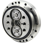
PRINCIPIO DEL REDUCTOR DE ENGRANAJES ARMÓNICOS
El impulso armónico fue inventado por el inventor estadounidense C. Walt Musser a mediados de la década de 1950.
1. Composición de la caja de cambios armónica
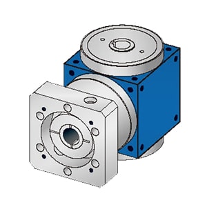
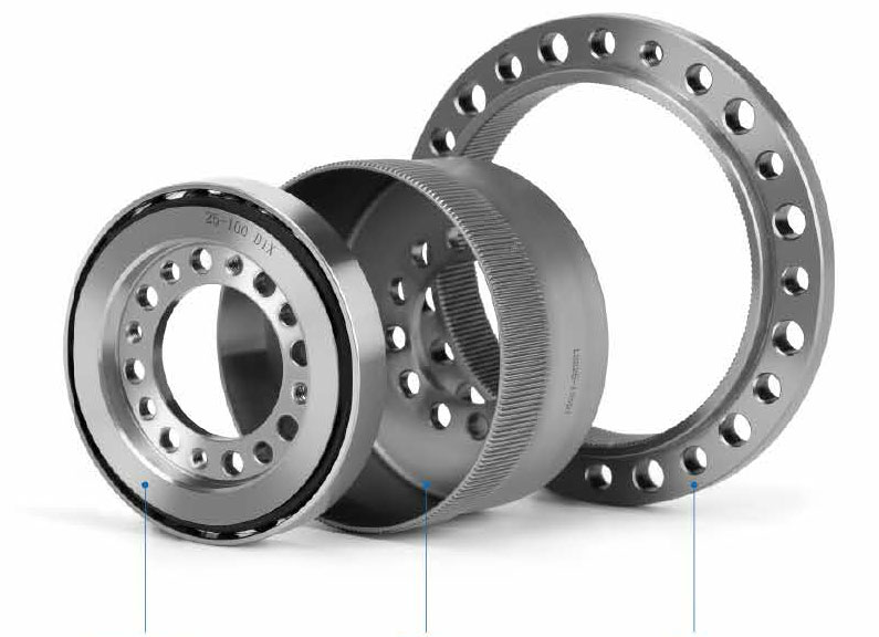
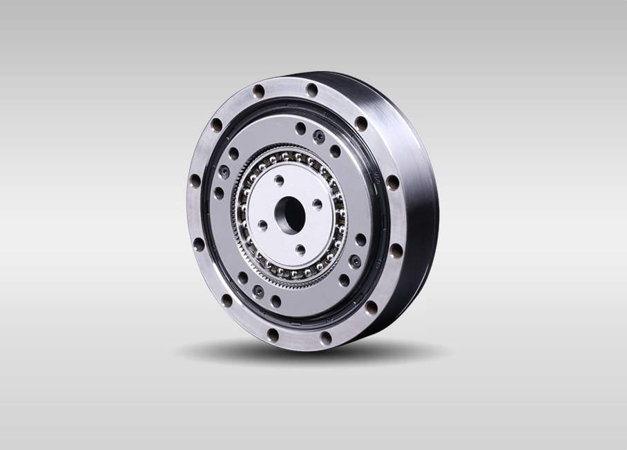
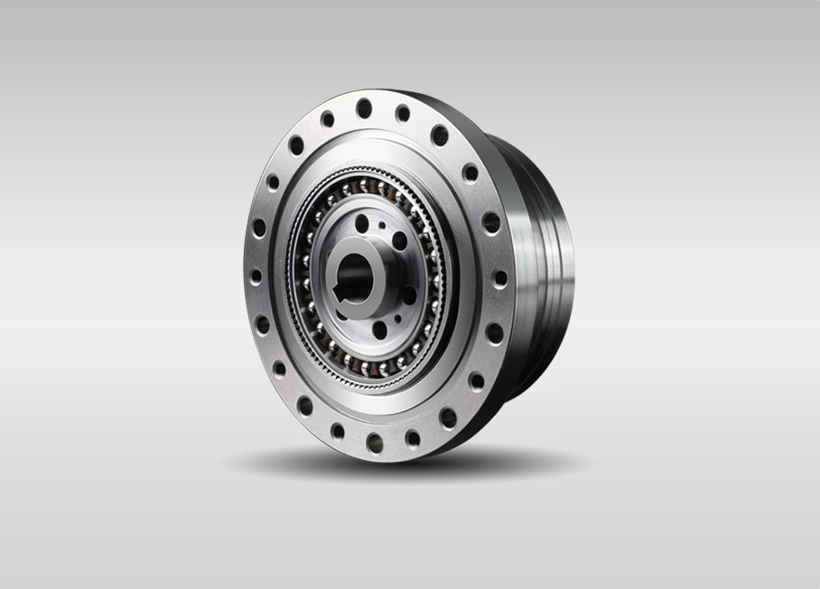
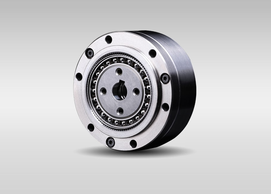
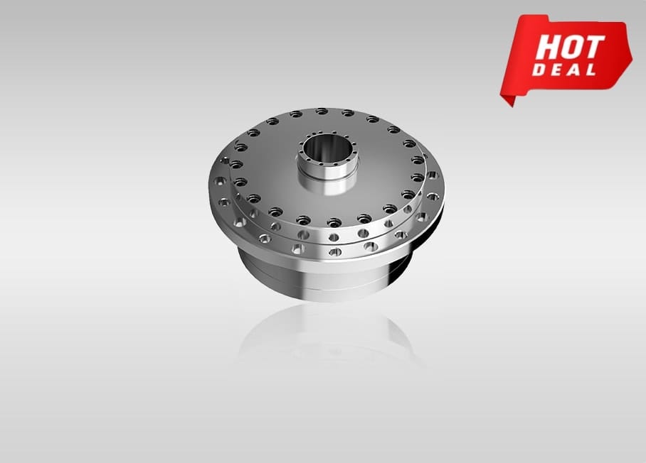
La caja de cambios armónica tiene tres componentes básicos: un generador de ondas, un spline flexible y un spline circular.
Generador de olas: está formado por un rodamiento de bolas y una leva elíptica. El generador de olas suele ir acoplado al extremo de entrada, el aro interior del rodamiento se fija alrededor de la leva provocando la El aro exterior del rodamiento se deforma hasta adoptar una forma elíptica.
Estriado flexible: es un componente elástico de paredes delgadas con dientes de engranaje en la superficie exterior. Generalmente se instala en el extremo de salida.
Estriado circular: es un anillo rígido de acero con dientes internos. Por lo general, tiene dos dientes más que la ranura flexible y generalmente está montado en una carcasa.
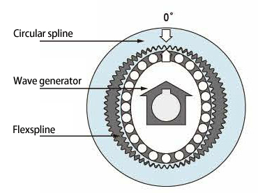
2. Principio de la caja de cambios armónica
Como reductor, la caja de cambios armónica suele estar en un estado como el siguiente: el generador de ondas impulsa, la ranura circular está fija y la ranura flexible es el extremo de salida.
Cuando el generador de ondas se coloca dentro de la ranura flexible, ésta se fuerza a adoptar una forma elíptica, lo que hace que los dientes de la ranura flexible se enganchen con el perfil del diente de la ranura circular a lo largo del eje mayor de la elipse, con los dientes completamente desconectado a lo largo del eje menor de la elipse.
La rotación del generador de ondas hace que la ranura flexible se deforme continuamente, los dientes cambian de estado operativo en el proceso de acoplamiento y desacoplamiento, por lo que se realiza la transmisión de movimiento entre el generador de ondas y la ranura flexible
3. Características de la caja de cambios armónica
 El generador de ondas fuerza la ranura flexible a una forma elíptica, lo que hace que los dientes de la ranura flexible se enganchen con el perfil del diente de la ranura circular a lo largo del eje principal de la elipse, con los dientes completamente desenganchados a lo largo de la Eje menor de la elipse.
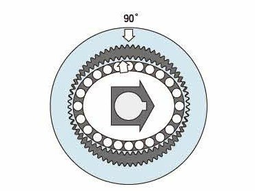 A medida que el generador de ondas gira en el sentido de las agujas del reloj con la ranura circular fija, la ranura flexible se somete a una deformación elástica y la posición de enganche de sus dientes se mueve girando en relación con la ranura circular.
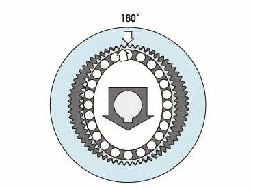 A medida que el generador de ondas gira 180 grados en el muelle, la ranura flexible se mueve en sentido contrario a las agujas del reloj un diente en relación con la ranura circular.
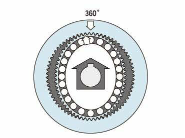 Por cada rotación completa en el sentido de las agujas del reloj (360 grados) del generador de ondas, la ranura flexible se mueve en sentido contrario a las agujas del reloj dos dientes en relación con la ranura circular porque la ranura flexible tiene dos dientes menos que allí. están en la spline circular. en general, este movimiento se trata como ejecución de salida.
Progreso de malla diente a diente
- La capacidad del dentado del engranaje aumentó un 15 %
- El aumento de temperatura disminuyó entre 8 y 10 grados
- Reducción del área de contacto con picaduras por fatiga del engranaje
- El tiempo de servicio superó las 15.000 horas
Acerca del perfil de diente WS
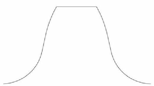
Hemos realizado algunas mejoras basadas en el perfil teórico tradicional de doble arco. El perfil del diente formado por la curva de arco continuo de dos curvas originales se optimiza como una curva de arco continuo con múltiples segmentos de curvatura. Para garantizar que los engranajes del reductor estén engranados correctamente, al mismo tiempo que se protege el riesgo de falla de la grasa después de exprimirla al reducir la fricción de deslizamiento relativa.
Basado en δ forma del diente, la capacidad de carga aumenta en un 15%, el aumento de temperatura se reduce entre 8 y 10 grados, el área de contacto de picaduras por fatiga del engranaje se reduce en más del 30%, el funcionamiento continuo y la vida útil superan las 15000 horas, lo que mejora la Rendimiento general de la caja de cambios armónica.
Durante el desarrollo, la formación del perfil del diente blando puede determinarse mediante el desplazamiento radial del generador. Se pueden equipar diferentes relaciones de reducción de engranajes con varios perfiles de dientes y el juego de la malla se puede ajustar cómodamente según las condiciones reales. Mantenga la caja de cambios en las mejores condiciones de funcionamiento.
Acerca del reductor armónico Fubao
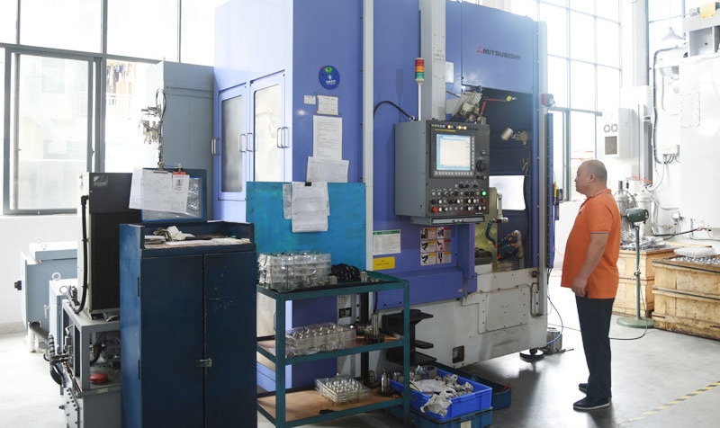
Dongquan Fubao Motor Technology Co., Ltd, es una empresa especializada dedicada a la investigación y el desarrollo de cajas de cambios armónicas de alta precisión. La empresa cuenta con 30.000 metros cuadrados de planta estándar, utiliza los mejores equipos de producción e inspección del mundo y cuenta con un estricto control de calidad en todos los aspectos, desde las materias primas hasta los productos terminados, para garantizar la calidad de los productos.
Desarrollo completamente independiente, el departamento de I+D de la empresa. El centro D ha sido identificado como el centro provincial de R& D centro de empresas de alta tecnología. En el campo de la transmisión armónica, cuenta con varias patentes de invención nacionales y patentes de modelos de utilidad nacionales.
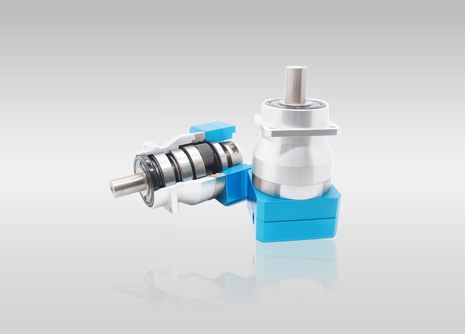
La caja de cambios armónica de precisión desarrollada y producida por nuestra empresa tiene las características de alta confiabilidad, alta precisión, alto torque, larga vida útil, gran relación de velocidad, pequeño volumen, etc. Los productos se utilizan ampliamente en los campos de robots, equipos aeroespaciales, máquinas herramienta CNC, equipos de fabricación de semiconductores, control de automatización de maquinaria de precisión, etc., y estamos comprometidos a cambiar el patrón de automatización mundial.
Naming Rules
| Series | Type | Reduction ratio(Note 1) | Structure Code | Style | |||||
|---|---|---|---|---|---|---|---|---|---|
| WSS WSN WSG WSD WFS |
11 | 50 | 80 | 100 | null | U: Completely unit C: Component |
I: Simple Standard Type II: Simple Cross Slider Type |
Blank: Standard M: Compact Mini |
|
| 14 | 50 | 80 | 100 | 120 | |||||
| 17 | 50 | 80 | 100 | 120 | |||||
| 20 | 50 | 80 | 100 | 120 | 160 | ||||
| 25 | 50 | 80 | 100 | 120 | |||||
| 32 | 50 | 80 | 100 | 120 | |||||
| 40 | 50 | 80 | 100 | 120 | |||||
Seal Ring's Size Description
| Series | Model | Circular spline | flex spline | ||
|---|---|---|---|---|---|
| Seal ring size | Slot size | Seal ring size | Slot size | ||
| WHT-I WUT-L |
14 | 36.5*0.6 | |
53*1.5 | |
| 17 | 45*1 | |
64*1 | |
|
| 20 | 54*1 | |
73*1.5 | |
|
| 25 | 68*1 | |
90*1.5 | |
|
| 32 | 88*1.5 | |
119*1.5 | |
|
| 40 | 108*1.75 | |
143*2 | |
|
Terms and Definitions
Starting torque: It is the minimum torque value applied to the input end at which the harmonic gearbox first starts to rotate with no load.
Backlash: The clearance between flex spline tooth profile and circular spline tooth profile.
Rated torque: It indicates allowable continuous output torque at rated input speed.
Permissible peak torque at start and stop: It's the maximum torque as a result of the moment of inertia of the output load during acceleration and deceleration.
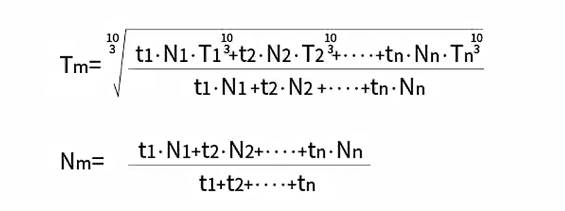
Permissible maximum value for average load torque: It's the maximum torque when the harmonic gearbox keeps continuous operation.
Permissible maximum momentary torque: It is the momentary peak torque the harmonic gearbox may be subjected to the event of a collision or emergency stop.
Permissible maximum input rotational speed: Don't exceed the permissible rating.
Permissible average input rotational speed: It's the average value of input speed.
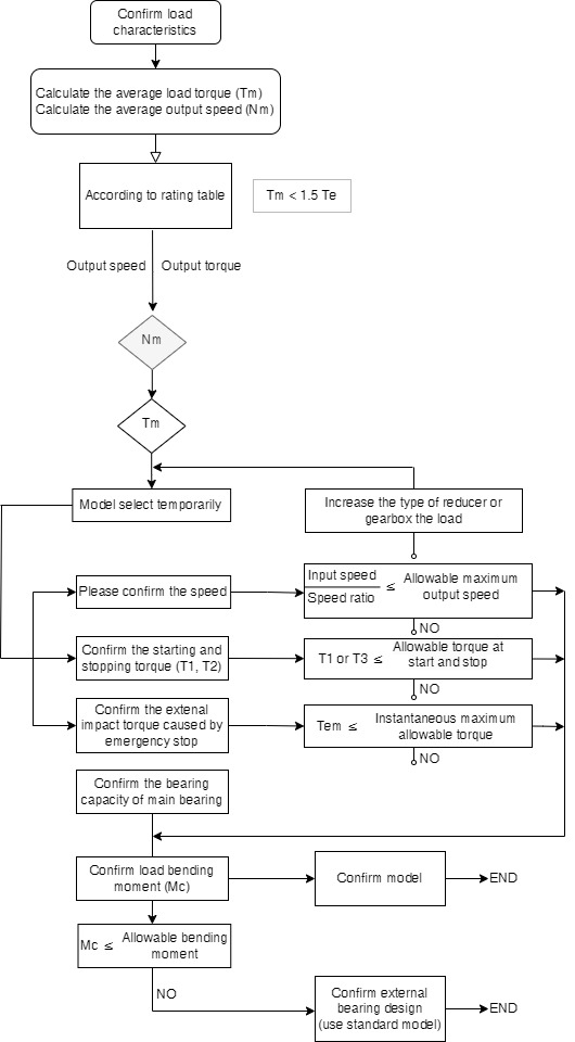
| At startup (MAX) |
When stable | When stopped (MAX) |
When emergency stop impact |
|
|---|---|---|---|---|
| Load torque (Nm) |
T1 | T2 | T3 | Tem |
| Speed (r/min) |
N1 | N2 | N3 | Nem |
| Time (sec) |
t1 | t2 | t3 | tem |
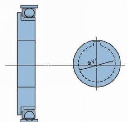
The wave generator includes a structure of a European-style coupling with a self-aligning structure and an integrated type without an automatic self-aligning structure, and varies depending on the series. For details, please refer to the outline drawing of each series.
Basic structure and shape of wave generator shown as below
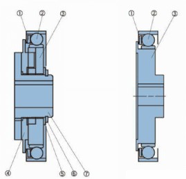
Structure of cross sliding block type-using European coupling structure
- Holder of flexible bearing
- Flexible baring
- Wave generator
- Cross sliding block
- Gasket
- Ring-shield
- Power input shaft
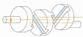
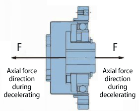
Axial force and axial fixation of wave generator
The axial force on wave generator begins to work due to elastic deformation of flex spline.
When used as a reducer. the axial force moves towards to the inside of the flex spline.
When used as a speed increaser, the axial forces movement is opposite to the direction of the deceleration.
The design of prevent axial force of wave generator shall be adopted under any conditions of usage.
Maximum apperture size of the unibody wave generator
The standard aperture of the wave generator has shown in the outline drawing, the alteration can be
made within maximum size range shown in the table.
We suggest to use GB standard for keyway size. The key's effective length dimension should be designed to fully withstand the value of the transmitted torque.
| Model | 11 | 14 | 17 | 20 | 25 | 32 | 40 |
|---|---|---|---|---|---|---|---|
| Standards size (H7) | 5 | 6 | 8 | 9 | 11 | 14 | 14 |
| Minimum size | - | 3 | 4 | 5 | 6 | 6 | 10 |
| Maximum size | - | 8 | 10 | 13 | 15 | 15 | 20 |
Installation Procedure
Installation of WSS series
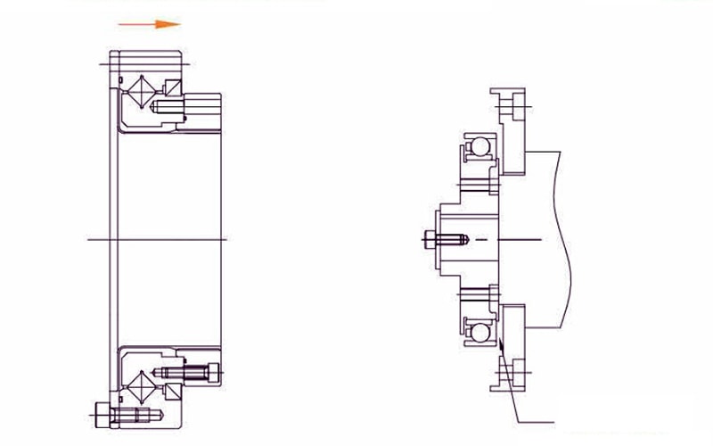
The first method of installation for WHT-I/II series reducer
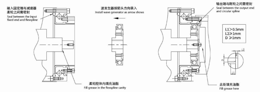
The second method of installation for WHT-I/II series reducer
 Fill grease here
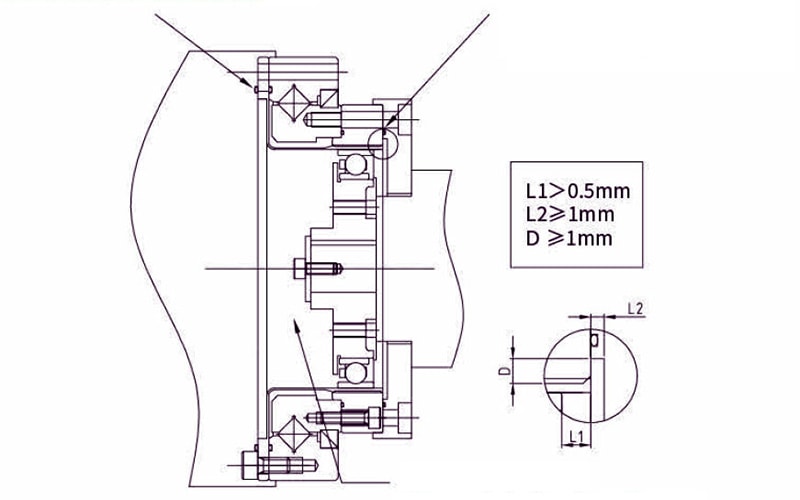 Fill grease in the flex spline cavity
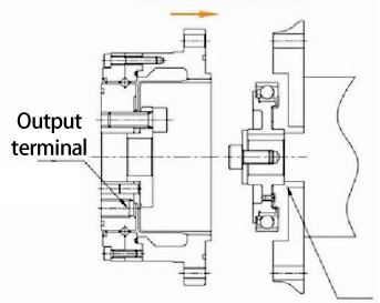
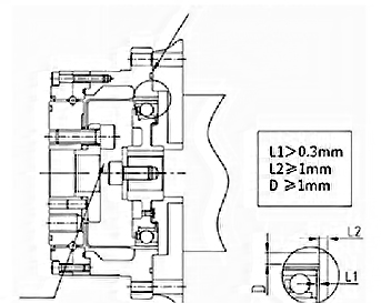
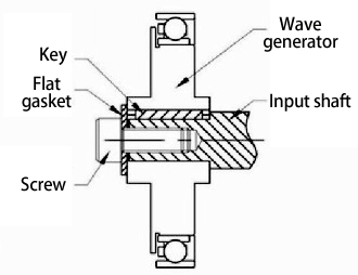
The connecting and fixing method of wave generator
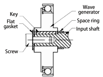
1. Input shaft has a shaft shoulder, it can be connected with wave generator directly. As shown in the figure.
2. Input shaft has a shaft shoulder, but it's too long. You can add a space ring on the shaft (the parallelism of space ring should be within 0.01mm), then connect and fix the wave generator. As shown in the figure.
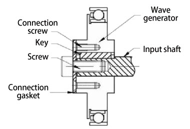
3. Input shaft has no shaft shoulder. Fix a connection gasket on the wave generator, then connect and fix with the input shaft. As shown in the figure.
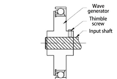
4. The fixing method is suitable for small models, optical axis input. Input shaft inserted into the wave generator, then connect and fix it through the thimble screw on wave generator. As shown in the figure.
Assembly Considerations
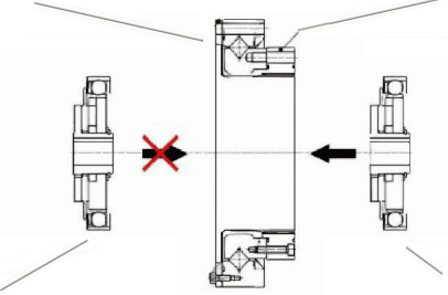
Assembly procedure
Instals the circular spline and flex spline on the device, and then instal the wave generator. Otherwise it may cause stuffing damage to the gear teeth or improper eccentric gear mesh. Please pay close attention to it.
Precaution on wave generator
1. Please avoid applying undue force on the bearing on wave generator during assembly. We suggest to rotate the wave generator while inserting, it will case the process.
2. If the wave generator does not have an oldham coupling, extra care must be given to ensure that concentricity and inclination are within the specified limits.
Precautions on circular spline
1. Mounting surfaces need to have adequate flatness, smoothness, and no distortion.
2. Especially in the area of the screw holes, burrs or foreign matter should not be present.
3. Please make sure the chamfering and avoidance machining are performed on the housing assembly, to avoid the interference with the circular spline.
4. The circular spline should be rotatable within the housing. Be sure there is no interference and it does not catch on anything.
5. When mounting the bolt, make sure the bolt hole is correct and aligned Bolts should rotate freely when tightening and should not have any irregularity due to the bolt hole being misaligned or oblique.
6. Don't tighten the bolts with the specified torque all at once. Tighten the bolts temporarily with about half the specified torque, and then tighten them with the specified torque. Tighten them in an even, crisscross pattern.
7. Avoid pinning the circular spline if possible as it can reduce the rotational precision and smoothness of operation.
Precautions on flex spline
1. Mounting surfaces need to have adequate flatness, smoothness, and no distortion.
2. Especially in the area of the screw h oles, burrs or foreign matter should not be present.
3. Please make sure the chamfering and avoidance machining are performed on the housing assembly, to avoid the interference with the circular spline.
4. When mounting the bolt make sure the bolt hole is correct and aligned. Bolt ros should tate freely when tightening and should not have any irregularity due to the bolt hole being misaligned or oblique.
5. Don't tighten the bolts with the specified torque all at once. Tighten the bolts temporarily with about half the specified torque, and then tighten them with the specified torque. Tighten them in an even, crisscross pattern.
6. Avoid unilateral meshing and deviation when assembling with circular spline.
Rust prevention
The complete assembly unit has no rust prevention on surface. Please daub anti-rust if needed. Besides, if an anti-rust product is needed, please contact with the authorized distributor.
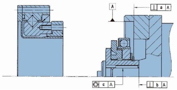
Assembly accuracy of WSS series
To make sure LSS series play its excellent performance when assemble, please make sure to use the following accuracy.
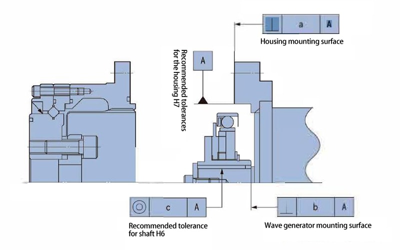
Recommended accuracy of the assembled housing
| Symbol / Model |
14 | 17 | 20 | 25 | 32 |
|---|---|---|---|---|---|
| a | 0.011 | 0.015 | 0.017 | 0.024 | 0.026 |
| b | 0.017 | 0.020 | 0.020 | 0.024 | 0.024 |
| (0.008) | (0.010) | (0.010) | (0.012) | (0.012) | |
| c | 0.030 | 0.034 | 0.044 | 0.047 | 0.050 |
| (0.016) | (0.018) | (0.019) | (0.022) | (0.022) |
Assembly accuracy of WHT series
To make sure LHT-I/II series play its excellent performance when assemble, please make sure to use the following accuracy.
| Symbol / Model |
14 | 17 | 20 | 25 | 32 | 40 |
|---|---|---|---|---|---|---|
| a | 0.011 | 0.015 | 0.017 | 0.024 | 0.026 | 0..026 |
| b | 0.017 | 0.020 | 0.020 | 0.024 | 0.024 | 0.032 |
| (0.008) | (0.010) | (0.010) | (0.012) | (0.012) | (0.012) | |
| c | 0.030 | 0.034 | 0.044 | 0.047 | 0.050 | (0.050) |
| (0.016) | (0.018) | (0.019) | (0.022) | (0.022) | (0.024) |
Industria de aplicaciones
Adecuado para una amplia gama de aplicaciones
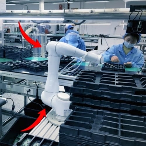
Robot cooperativo
Máquina multiarticular
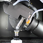
Máquina de corte por láser
Máquina herramienta, Rectificadoras
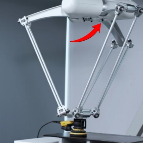
MANIPULADOR PARALELO
Robots Scara, mano de araña...
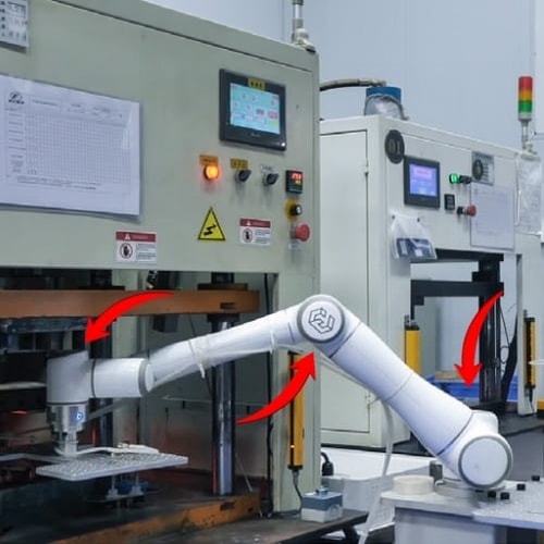
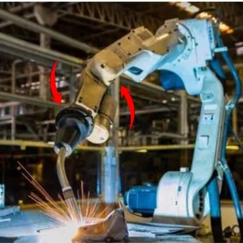
ROBOT INDUSTRIAL
Manipulador, robot de eje, etc.

ROBOT HUMANOIDE
Robot biónico, robots andantes.
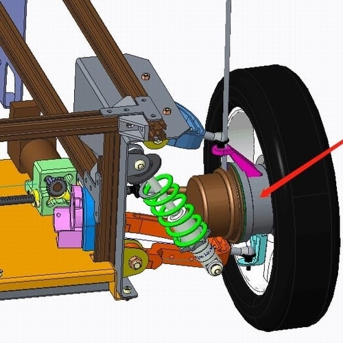
AGV CAE
Coche AGV para logística de almacén
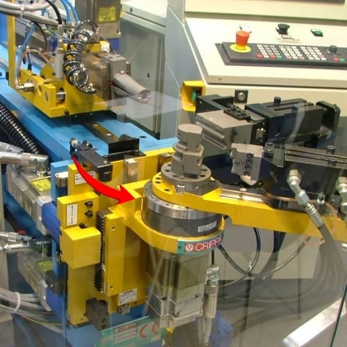
HERRAMIENTA DE MÁQUINA
Máquina dobladora de tubos...
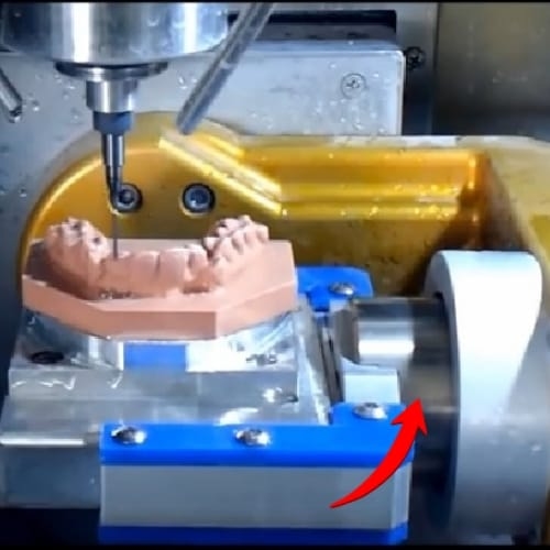
Máquina de tallado CNC
Tallado e impresión de dentaduras postizas.
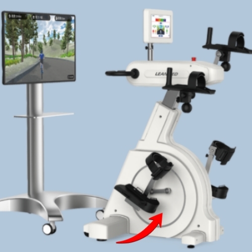
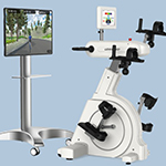
ROBOTS EXTERNOS
rehabilitación de peso..
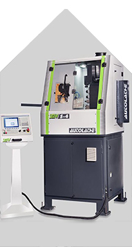
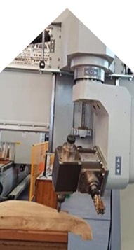
Fábricas de Fubao Mechanic Tech
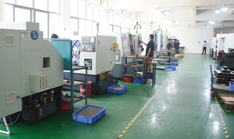
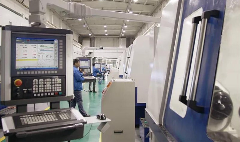
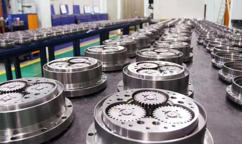


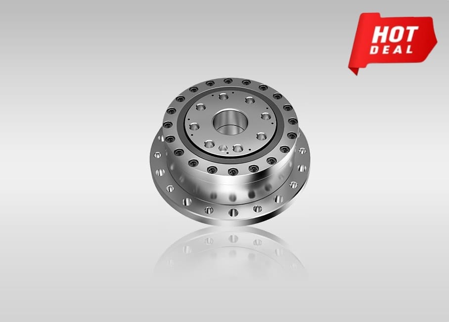

Ahora la oferta